07/04/22 - Currently the only modern pump system available for the DeLorean. Fit's all models produced from 1981-83 (the only years the car was produced)
DeLorean Industries updated fuel pump configuration (GEN3). Direct replacement for failure prone stock configuration. The system is based around a high quality Delphi pump unit meeting OEM manufactures who demand strict reliability standards. Originally released in 2010 with our SPEC EFI fuel injection solutions to combat ethanol blended fuel usage. Note that sub-standard knock off kits with low quality look alike components are often mistaken and misrepresented as the same quality as this system. Our product offering is only available directly from us and not available through third party retailers.
All in one pump/sender configuration with digital controlled gauge. Includes updated pump with sending unit, Fuel gauge control module, sealing ring, harness, premium AN fitting braided lines, stainless 304L high flow check valve and V band clamp. Bespoke DeLorean specific electronics developed in the United States in conjunction with DM- Eng.
How this system differentiates from the rest?
__ Billet anodized -6 AN high flow one way check valve with 304L internals attached via stainless steel AN fittings. (Knock off option uses a under sized bore brass check valve secured with hose clamps)
__ Braided stainless steel feed and return lines with stainless steel fittings, billet quick disconnect points at pump assembly. True bore 5/16 internal hose to prevent flow restriction. (Knock off option option uses rubber fuel line with hose clamps connected to fittings designed for use with nylon hose. Requires replacement every few years due to hose degradation)
__ DM- Eng integrated electronics sealed in billet aluminum anodized case with mounting system. (Knock off option uses low quality electronics with high failure rate due to mounting location. Requires use of zip ties to secure to filler neck hose)
__ Premium Delphi FG 0089 pump and sender unit. (Knock off option uses highly documented unit available wholesale for under $20.00 per unit)
__ Weather pack premium connection points removing failure prone Lucas factory pins. (Knock off utilizes factory style connector and relies on factory side of connector being in usable condition.)
__ All new components no cores required. (Knock of requires sending in old connector and other misc fuel tank components)
__ Backed by industry leading warranty and support by pump manufacture Delphi. (Knock off has strict short term warranty terms from date of purchase)
INSTRUCTIONS - ALSO SUPPLIED WHEN PURCHASED AND AVAILABLE VIA PDF
FUEL PUMP WITH INTEGRATED SENDER INSTALLATION INSTRUCTIONS
PART # K111085
Congratulations on purchasing a DeLorean Industries Fuel Pump with integrated sender tank system. This stand alone system is designed to replace all of the high failure rate rubber components located inside of the fuel tank to the hard line connection points and implementing a state of the art sender solution. The premium pump supplied and related components in direct contact with fuel are compatible with blended fuels also known as “ethanol”.
Read the instructions in their entirety before attempting this process. If anything is left to question contact us directly via email. We do not offer phone tech support as we find that it crucial to have a reference in writing for you to use.
The tank must be completely emptied at the start of the installation process. If your current pump has failed you still must siphon out all remaining fuel. The tank can hold on average 13.5 gallons of fuel. If the tank is heavily contaminated after draining the old fuel you must
completely clean the tank. Failure to do so will void the pumps warranty. The best solvent available for cleaning hard deposits is acetone. We strongly suggest referring to the chemical manufactures MSDS prior to using for all applicable safety precautions.
Gasoline is extremely dangerous. Always have a Class B fire extinguisher available when servicing fuel system components. While we hope you are a grown adult who has read enough warning stickers while at the pump filling your car, you can never be too careful. Remove all other flammables from around the work area. Don't smoke or use open flame. If your garage is heated remember gasoline fumes hug the floor. A well ventilated work area is not optional. Failure to adhere to the above will result in serious life changing injuries and most likely death.
INSTALLATION PREPERATION
-
Disconnect battery (wrap positive terminal to prevent contact)
-
Remove trunk contents and spare tire board cover and tire. Remove tank access plate complete.
-
Remove factory pump assembly by loosening large hose clamp. Pull assembly up and out and cut lower pick up hose.
4. remove 10mm nut and washer attaching factory pick up assembly to molded stud point at base of tank. Remove factory baffle and pick up. Discard.
5. Clean inside of tank complete. NOTE: Let someone know you are doing this. IE a loved one or neighbor. Keep cell phone within reach. If you insert your arm past the elbow joint you run the risk of getting stuck. Yes, this sounds silly but it is very easy to get into the intense cleaning of the fuel tank and find yourself planking over the right front fender.
-
Cut factory feed/return line flexible sections from barb connections on passenger side frame rail. Discard pump assembly and feed/return lines, stock sending unit and all tank pick up components.
-
Remove factory tube nut barbs from frame rail connections. While holding barb assembly end loosen 17mm nut and slide towards rear of car on hard line. This will expose the rear section of the tube nut sleeve. With needle nose vice crimps squeeze the barb with light pressure to prevent from spinning on line. Using the wrench holding the front barbed fitting rotate to break free from the crush sleeve.
NEW COMPONENT INSTALLATION
-
Install M14- AN fitting line adapters using 17mm tube nuts and installed crush sleeves. Take care not to break the fuel hard lines from the plastic clips securing the lines to the top of the frame.
-
The pump assembly is supplied with the float wire detached to prevent damage during shipping. This is installed on the pump housing by inserting the metal wire into the center hole of the pump sender sensor. DO NOT apply pressure to the electrical contact area of the level sensor wiper arm during installation. Applying pressure to this will damage the electrical contacts for the sending unit. The float arm assembly must be fully seated to prevent coming loose in the tank. After installation make sure that the float arm does not bind and freely travels to it's maximum and minimum settings.
-
The supplied updated connector and wiring ends are intended to create a water tight seal. We suggest cutting the factory harness on the car side of the failure prone two pin Lucas connector. This is a high failure point for voltage issues to the pump assembly. Using the supplied water tight crimp connectors make the following connections.
Two pin connector
__install the gray/red harness connector wire to the factory purple/white wire. (Pump power)
__Install the black/black and orange wire to the factory purple and black wire. (Ground)
Three pin connector
__Install the black wire to the factory black wire on the sender 3 harness.
__Install the gray wire to the factory green/black wire on the sender harness.
__Install the white wire for the low fuel light to the factory green/orange wire on the sender harness.
RECOMMENDED FUEL SENDER SYSTEM TEST PROCEDURE
While this is not required, we highly recommend testing the fuel gauge system after preforming the below wiring steps. There are a variety of concerns external to the new sending unit that can cause issues. It is easier to perform a “dry test” of the system to confirm nominal operation of all integrated harness circuits, cluster printed circuit board and gauge assembly.
___ With the above wiring completed, disconnect the RPM relay behind the passenger seat
___disconnect the two pin connector on the fuel pump assembly in the lower section of the pump housing. (black and gray wires) Doing this prevents power from going to the pump without fuel in system.
___Plug main harness into pump assembly.
___ With key in off position, install two wire jump across RPM relay. This will connect the brown 12v hot wire to the purple/white fuel pump circuit.
___ With the sending unit float at it's lowest point of travel turn the key on. The gauge will now go to empty and settle once the unit heats. Once confirmed turn the key to the off position.
___ With the sending unit float at it's highest point of travel turn the key on. The gauge will now go to full and settle once the unit heats. Once confirmed turn the key to the off position.
___ Remove the RPM relay jumper and leave RPM relay disconnected, install two wire harness on pump assembly. The system has now been tested for proper gauge function and can be assembled.
PUMP ASSEMBLY INSTALLATION
11. Prior to installing the pump assembly in tank make sure that the free floating static wire located towards the drivers side is bent out of the way as far as possible towards the drivers side. This will prevent interference with the integrated units pump sending wire and float. Install pump assembly in tank. The black supplied seal seats on the upper tank ring edge. This must be slid over the pump assembly first. The pump lower housing features a purpose built flat spot around the lower diameter. This is for clearance around the factory stud in the base of the tank. Note installation pictures on product listing for proper pump orientation. Tighten supplied clamp assembly while pushing down on unit. Proper orientation of clamp and pump assembly pictured on product listing for reference.
Blanking cap and O ring installation on the factory sending unit port is accomplished by screwing the 6 TPI cap and o ring onto the factory tank. In some instances especially on very early cars this may not want to seat/tighten or seal properly. If this occurs, contact us directly for O ring options and proper installation.
12. The supplied feed and return lines are state of the art mil spec braided stainless woven, nylon PTFE fuel resistant true bore ID, with stainless ends. The feed line features an in line check valve with 304L stainless internals. The lines are shipped assembled “loose”. All connections must be tightened. The return line is identified by being one piece without the check valve. The lines can not be interchanged at the pump connection point as they feature different quick disconnect line end sizes. Return is to the front of the car with the feed at the rear of the car.
13. Connect the AN line fittings to the already installed adapters at the frame hard line connection point. The connection point closest to the inside of the car is the feed line. The connection closer to the outside is the return. Mixing these connections with produce a no start condition
14. Test system for leaks prior to running car. This is accomplished by jumping the RPM relay in the fuse compartment. With a 20 amp fused jumper, connect the brown wire to the purple and white wire. (same jumper procedure used for sending gauge test)
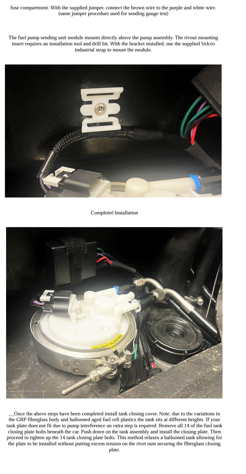
15. The fuel pump module is mounted directly above the pump assembly. (detailed pictures of install are posted on the product listing for reference) The rivnut mounting inserts require a M5 installation tool and 19/64 drill bit.
16. Once the above steps have been completed install tank closing cover. Note: due to the massive variation in the GRP fiberglass body the tank sits at any number of different heights. If your tank plate does not fit due to pump interference an extra step is required. Remove all 14 of the fuel tank closing plate bolts beneath the car. Push down on the tank assembly and install closing plate. Then proceed to tightening up the 14 tank closing plate bolts.
ADDITIONAL GAUGE ELECTRONICS DATA- DM-ENG MODULE
Calibration (Custom if required due to gauge resistance issues)
Note, to open the unit remove the end with the wires.
When calibrating the gauge, it’s important to get your eyes directly over the gauge needle. If you are looking at an angle you won’t be able to calibrate exactly. Jumper J1 is shorted on both pins to put the unit into calibration mode. Move the jumper to only one pin (hanging off one side) to put the ECU into normal run mode.
Setting the low and high gauge adjustment.
Jumper J1, turn the POT R6 fully counter clockwise, the gauge should move to empty. The low fuel light will also come on so you can verify that is working. Let the gauge heat up for about 10 minutes. Adjust R3 to get the gauge exactly on the empty line.
Now move POT R6 fully clockwise. Your gauge should now move to the full mark. It takes about one minute for the gauge to settle. Adjust R1 to get the gauge exactly on the full line. Make very small adjustments and wait for the gauge to settle. The full end of the gauge has very slow movement.
Checking the ¼ mark accuracy.
Move POT R6 full counterclockwise and then slowly turn a little clockwise until your gauge moves from empty to the ¼ full mark. Note how close the needle points to the ¼ mark. Now slowly turn R6 some more clockwise until the gauge moves to the ½ full mark. Then again turn R6 until the gauge moves to the ¾ mark.
Adjusting the sensor calibration.
These are adjusted via POTs R2 and R9 (rev A boards R8). This sets your high and low reading in case your sensor is not moving the full range empty or full. To make these adjustments would require the car to have a full tank and an empty tank. This can also be tested as outlined above with the pump and sending unit removed.
Gauge filtering.
When not in calibration mode, R6 provides the user to select one of three filtering settings. Filtering is required to not show “tank slosh” when gas in your tank is moving back and forth. Full counterclockwise set on R6 provides very little filtering and is used mostly for testing a new sensor. Setting R6 to mid position provides about 10 times the filtering of the first setting. Setting R6 full clockwise provide filtering about 10 times the second setting. This last setting is very long but will keep up to fuel usage as long as you don’t develop a leak in the fuel system.
Note when the unit is first power on the gauge will move quickly to what the sensor is reading. Assuming you are parked level it will be accurate very quickly. If testing your sender, you will need to turn power on and off to read a quick value or you could rotate R6 full CCW. But remember to move it back full CW when you’re done.
Attention California Customers - WARNING: This product can expose you to chemicals including lead, which is known to the State of California to cause cancer and birth defects or reproductive harm. For more information go to www.P65Warnings.ca.gov.
6 Reviews Hide Reviews Show Reviews
-
Modern Fuel Pump System
Quality components, fits perfectly, easy to install, would recommend an extra foot on the ground wire for routing to chassis. Way better than the other offerings out there. Thanks
-
Quality blew me away
It isn't until you get this in your hands you can appreciate the quality designed into this solution. The pump itself is heavy and substantially built. The fuel lines are impressive and all the connectors give a quality look to the completed job. Get the weatherpack tool if you don't have one. The entire product is well thought out and fits perfectly. I have a lot more confidence in my fuel delivery system with this along with new engine compartment fuel lines.
-
Fuel Pump
This pump setup is great to replace the faulty OEM setup. It was easy to install with good directions.
-
Fuel pump system
I was hesitant to spend the money for this kit but I am glad I did. It is really good set up that should work well.
-
Perfect fit, well designed
Easy instructions, the upgrade is recommended. Pump, lines and gauge sender
-
Great Pump, Great Sender
Very simple to convert over to if you have a factory pump. Went on a 400 mile roadtrip with this pump and had no issues. The fuel gauge reads pretty accurate too. Highly recommended!